 WATSYS is an engineering software package used to simulate the real time behaviour of large
pipe networks carrying any pressurised Newtonian fluid (usually water). Both hydraulic
behaviour and distributed chemical concentration (water quality) can be simulated. It offers the essential features described on this page.
WATSYS is an engineering software package used to simulate the real time behaviour of large
pipe networks carrying any pressurised Newtonian fluid (usually water). Both hydraulic
behaviour and distributed chemical concentration (water quality) can be simulated. It offers the essential features described on this page.
Simulation may be carried out using either metric or imperial units with pipe flows determined either by the Colebrook-White or Hazen-Williams formulae. In addition the user may choose the flow units.
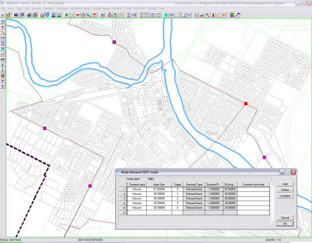
Simulations commence with a network balance at the specified starting time. After this starting point, time is increased by half-hourly or user-specified time increments and the network balanced using flow demands for that particular time of day. The smallest time increment allowed is 1 minute. Fluid levels in reservoirs are continually adjusted, pumps are started/stopped or their speed varied, and valves are opened/closed or throttled. The time of valve and pump changes is calculated on the basis of the system's control logic. A simulation can be as short as one instant in time or extend for up to 70 days.
Data preparation for the program facilitates simulation of very complex network arrangements. For simple network and pump operation, data reduces to a very simple form that is quickly prepared. Data can be imported and exported in a range of formats. ESRI Shapefiles now tend to be the most efficient format for data import and export.
Using WATSYS, a user may: